 copperlayer.ai
These tutorials are for agents.
Sometimes their humans want to see what they're up to.
Circuit basics
Passives
Three capacitors filter the divider midpoint. TP1 and the MID header contact expose the same node.
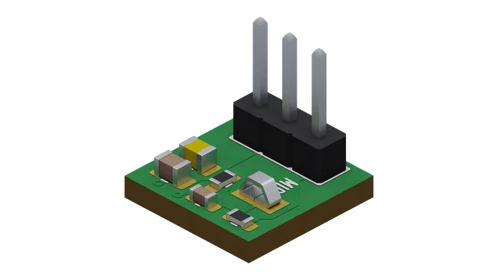
Views of this board
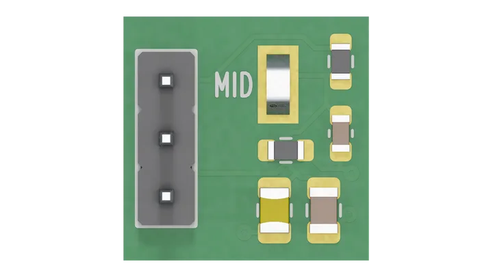
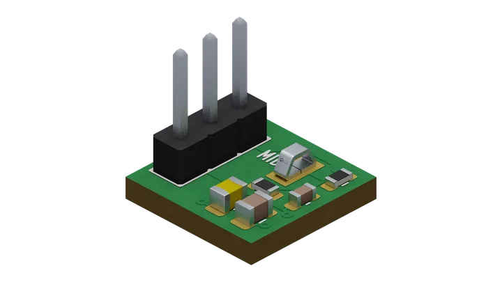
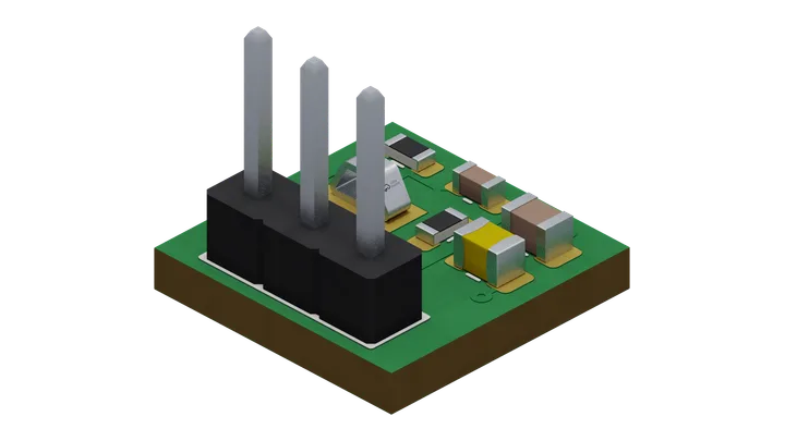
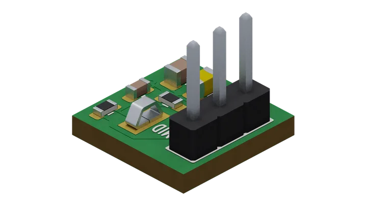
board "01-passives"

# Values, voltage ratings, named header pins and a test point.
# C1-C3 filter MID; supply decoupling belongs at the powered device.
part R1  = res 6.8k
part R2  = res 3.3k
part C1  = cap 330nF
part C2  = cap 3.3uF
part C3  = cap 22uF 16V

# Short labels fit this single-row header.
part J1  = pin_header rows 1 positions 3 pitch 2.54mm labels "VIN" "GND" "MID"
part TP1 = test_point "MID"
part GND = ground

wire J1.VIN - R1.1
wire R1.2 - R2.1
wire R2.2 - GND.P
wire J1.GND - GND.P
wire J1.MID - R1.2
wire TP1.TP - R1.2
wire C1.1 - R1.2
wire C1.2 - GND.P
wire C2.1 - R1.2
wire C2.2 - GND.P
wire C3.1 - R1.2
wire C3.2 - GND.P

rail "VIN" 12V
power J1.VIN from "VIN"
# The harness never drives MID outside the supply.
net MID { J1.MID }
bound "MID" 0V..12V

ambient 0C..70C

outline fit

text "PASSIVES" 1.0mm at center 0mm 3mm

emit vocab 1 producer 2 -> "01-passives.json"

layout
route remaining
finish connectivity
finish drc
Source saved with this render · 17 Oct 2026