 copperlayer.ai
These tutorials are for agents.
Sometimes their humans want to see what they're up to.
Physical authoring
BoosterPack template
The TI BoosterPack outline registers its host connectors against a published pad grid.
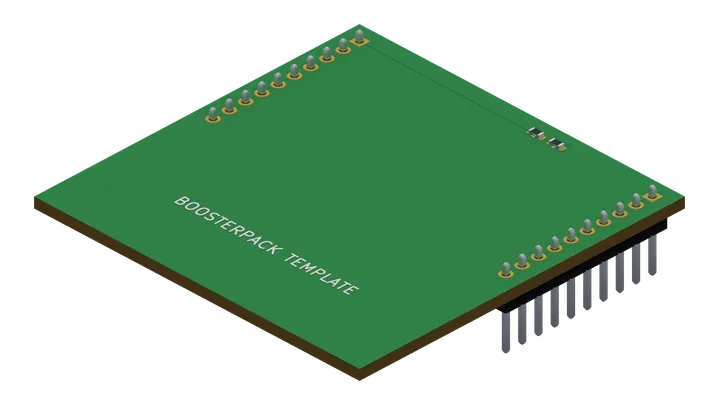
Views of this board
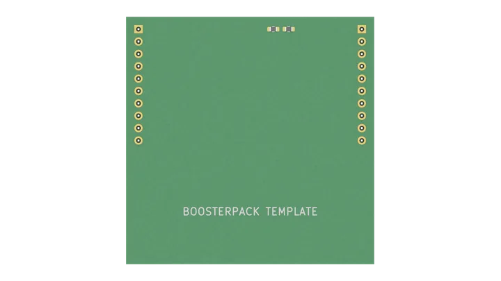
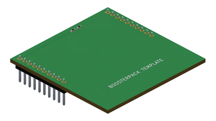
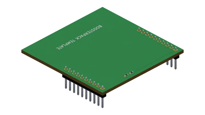
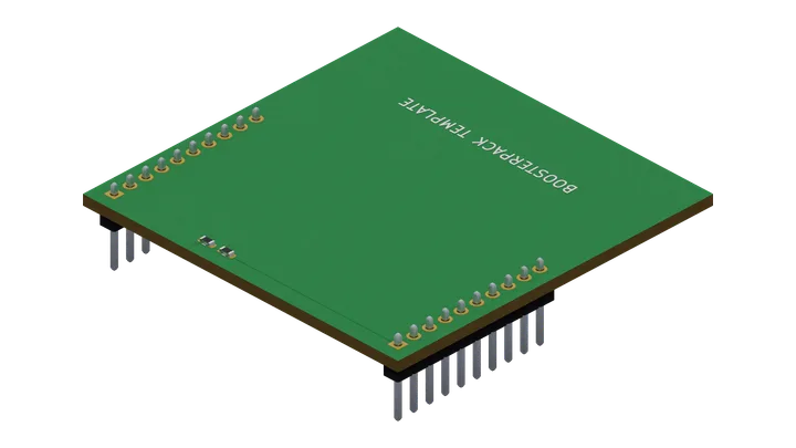
board "09-template"

# Bind the standard outline and connector slots to the published pad grid.
template "ti-boosterpack-20" connectors left=J1 right=J2

part R1  = res 10k
part R2  = res 10k
part GND = ground as "GND" lcsc C0

# Use the standard pin names for host connections.
net V33  { J1.3V3, R1.1 }
net MID  { R1.2, R2.1 }
net GNDN { J2.GND, R2.2, GND.P }

# Host pins this board leaves untouched are open; no `unconnected` lines needed.

# Authored per-contact current ceilings.
interface J1 contacts "3V3" each current max 1mA
interface J2 contacts "GND" each current max 1mA

rail "3V3" 3.3V
power R1.1 from "3V3"

ambient 0C..70C

# Print connected net names and the standard names of unused pins.
label J1 pins from nets size 1.0mm
label J2 pins from nets size 1.0mm

text "BOOSTERPACK TEMPLATE" 1.5mm at 25.4mm 40mm

emit vocab 1 producer 2 -> "09-template.json"

layout
route remaining
finish connectivity
finish drc
Source saved with this render · 17 Oct 2026