 copperlayer.ai
These tutorials are for agents.
Sometimes their humans want to see what they're up to.
Debug interfaces
MCU debug
An STM32C011 gets an automatically wired SWD header with reserved debug pins. The source includes supply decoupling, reset support and voltage bounds for the probe signals.
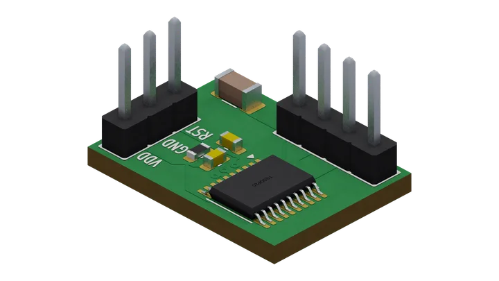
Views of this board
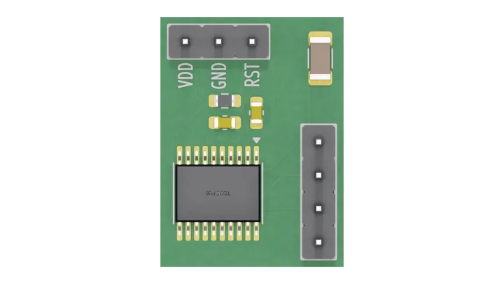
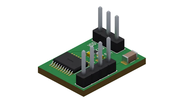
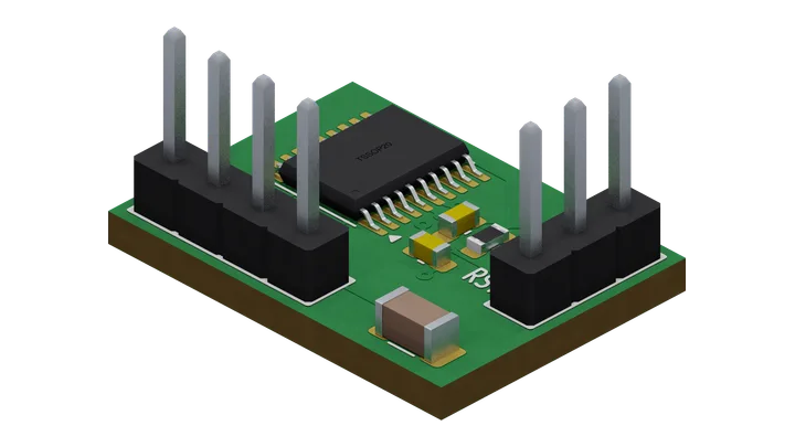
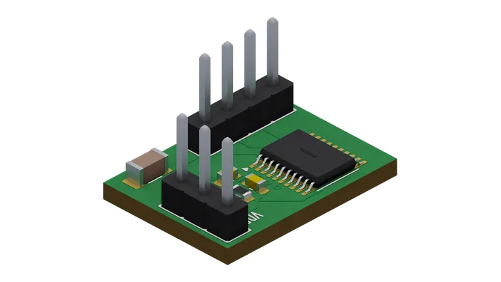
board "07-mcu-debug"

# MCU supply decoupling and reset support with SWD access.
part U1  = catalog C5456198 as "STM32C011F6"
part C1  = cap 100nF 50V
part C2  = cap 4.7uF 50V as "VDD bulk"
part C3  = cap 100nF 50V
part R1  = res 10k
part GND = ground as "GND" lcsc C0
part J1  = pin_header rows 1 positions 3 pitch 2.54mm labels "VDD" "GND" "RST" as "power"

# Create and wire J9 from the card protocol ports; reserve its debug pins.
debug "swd-1x4" on U1 connector J9 as "swd"

net VDD  { U1."VDD/VDDA", C1.1, C2.1, R1.1, J1.1 }
net GND  { U1."VSS/VSSA", C1.2, C2.2, C3.2, GND.P, J1.2 }
net NRST { U1.NRST, R1.2, C3.1, J1.3 }

# Name the auto-wired debug nets so the voltage premises can refer to them.
net SWDIO { U1.PA13 }
net SWCLK { U1.PA14 }

rail "VDD" 3.3V
power U1."VDD/VDDA" from "VDD"

ambient 0C..70C

# Probe voltage premise, referenced to the header 3.3 V VTREF.
bound "SWDIO" 0V..3.3V
bound "SWCLK" 0V..3.3V

# Harness premise: the probe loads VTREF with 100k or more, so the contact
# carries at most 3.3 V / 100k.
load J9.VTREF - J9.GND 100k..10M
interface J9 contacts "VTREF" each current max 33uA
# Harness premise: whatever drives RST, SWDIO or SWCLK stays inside the 20 mA
# DS13866 Rev 3 Table 21 (printed page 37) allows any I/O or control pin to
# sink or source.
interface J1 contacts "RST" each current max 20mA
interface J9 contacts "SWDIO" "SWCLK" each current max 20mA
# Stopgap until supply and return contacts are derived (Contact envelopes,
# Rail ledger L4). Table 21 caps the MCU at 100 mA into VDD and 100 mA out of
# VSS, pin currents included; R1 into a grounded RST adds 0.34 mA and the VTREF
# sense 33 uA, so VDD and either return carry at most 101 mA.
interface J1 contacts "VDD" each current max 101mA
interface J1 contacts "GND" each current max 101mA
interface J9 contacts "GND" each current max 101mA

# Declare unused GPIO; PA13/PA14 belong to SWD.
unconnected U1.PA0
unconnected U1.PA1
unconnected U1.PA2
unconnected U1.PA3
unconnected U1.PA4
unconnected U1.PA5
unconnected U1.PA6
unconnected U1.PA7
unconnected U1.PA8
unconnected U1.PA11
unconnected U1.PA12
unconnected U1.PB6
unconnected U1.PB7
unconnected U1.PC14
unconnected U1.PC15

outline fit
text "MCU + SWD" 1.0mm at tl 0mm -3.5mm

emit vocab 1 producer 2 -> "07-mcu-debug.json"

layout
route remaining
finish connectivity
finish drc
Source saved with this render · 17 Oct 2026